3nm vs 5nm Filters: Choosing the Right Narrowband Filter for Astrophotography
When it comes to narrowband filters for astrophotography, the choice between 3nm and 5nm filters can significantly impact the quality and characteristics of your images. Both have their advantages and trade-offs, and understanding these can help you make an informed decision. In this post, we’ll delve into the differences between 3nm and 5nm filters, the math behind their performance, and the pros and cons of each.
One thing I want to state up front is that I’ll often just use the words “Ha”. I only do this so I don’t have to spell out every filter so in your head you can think of “Ha, Sii or OIII” when thinking in terms of targeted signal.
Understanding Narrowband Filters
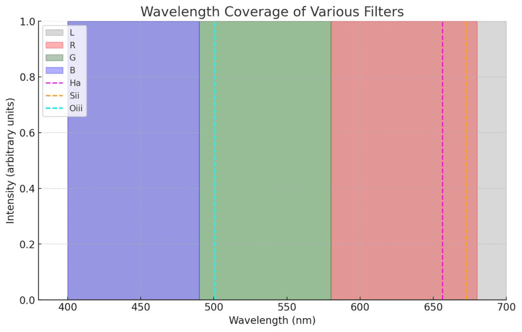
Narrowband filters are designed to isolate specific wavelengths of light emitted by celestial objects, such as hydrogen-alpha (Ha), oxygen-III (OIII), and sulfur-II (SII). By blocking out all other wavelengths, including light pollution, these filters allow astrophotographers to capture stunning details of nebulae and other deep-sky objects.
While we say Narrowband filters block out light pollution, they only block out large portions of the spectrum of light pollution to reduce its total impact.
Filters don’t actually work by “filtering” like we think of filters filtering out water or air.
What narrowband filters do, is target specific band passes at narrow bandwidths within the standard frequency of light.
How do filters work?
Narrowband filters are typically made using interference coatings. These coatings consist of multiple thin layers of dielectric materials with different refractive indices.
When light passes through these layers, some of it is reflected at each interface between the layers. The constructive and destructive interference of these reflections determines which wavelengths of light are transmitted and which are blocked.
Constructive Interference: For light at the specific wavelength that the filter is designed to transmit, the reflected waves from the different layers interfere constructively. This means that the peaks of the waves align and reinforce each other, allowing the light to pass through the filter.
Destructive Interference: For light at other wavelengths, the reflected waves interfere destructively. This means that the peaks of one wave align with the troughs of another, effectively canceling each other out and preventing that light from passing through the filter.
The thickness and refractive indices of the layers in the filter are precisely controlled to determine the specific bandpass (the range of wavelengths that are transmitted).
High-quality narrowband filters typically have very narrow bandpasses, such as 3nm to 7nm, which means they allow only a small range of wavelengths to pass through while blocking the rest.
The Math Behind Narrowband Filters
Bandwidth:
- 3nm filters: Allow a 3nm wide range of wavelengths to pass through.
- 5nm filters: Allow a 5nm wide range of wavelengths to pass through.
Signal-to-Noise Ratio (SNR):
- Narrower filters (3nm) can provide a higher signal-to-noise ratio by blocking more unwanted light, including light pollution and skyglow.
- Wider filters (5nm) let in more light from the target object, potentially capturing more signal but also allowing more background noise.
I think it’s important to highlight these statements because they are true, and I want to make sure people know they are true before we get to the part where lots of people dispute my conclusion.
So, here’s the math to describe the SNR and the benefit of sky glow in comparison to each other. I’ve simplified at a bit.
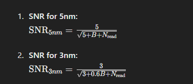
B = background/skygow (you can use whatever number you want)
N = read noise of your sensor. On our observatory this is 1.5 electrons.
So if we solve this equation with say, a huge background of 1000 we get
SNR for 5nm = .157
SNR for 3nm = .122
Notice anything? More on that later. Let’s reiterate the pros and cons.
Pros and Cons of 3nm Filters
I’ll try and just keep it pretty simple in terms of bullet points. The filters largely do the same thing, just their bandwidth differs and that bandwidth has side effects we’ll talk about in more detail later.
Pros:
- Higher Ha Signal Ratio: By isolating a narrower band of light, 3nm filters significantly reduce light pollution and skyglow, resulting in cleaner images with higher Hydrogen Alpha contrast.
- Better Detail: The higher Ha signal and reduced background noise can help in capturing finer details of faint nebulae and other deep-sky objects. There are some tradeoffs to be aware of here.
- Ideal for Light-Polluted Skies: 3nm filters are particularly effective in urban or light-polluted areas, where blocking as much unwanted light as possible is crucial.
Cons:
- Longer Exposure Times: Because 3nm filters allow less light to reach the sensor, longer exposure times are required to gather sufficient signal.
- Higher Cost: 3nm filters are generally more expensive due to the precision required in their manufacturing.
Remember the cons, we’ll kind of clarify how they’re not really a con IMHO.
Pros and Cons of 5nm Filters
Pros:
- Shorter Exposure Times: The wider bandwidth allows more light to reach the sensor, reducing the exposure time needed to gather sufficient signal. The “Swamp factor” of a sensor is lower time. The signal rate is higher. The width of the filter allows more total photons.
- More Affordable: 5nm filters tend to be less expensive than their 3nm counterparts, making them a more budget-friendly option.
- Broad Application: Suitable for a range of observing conditions, including moderately light-polluted skies.
Cons:
- Lower Ha (or Sii/OII) Signal: The wider band allows more unwanted light to pass through, which can reduce the signal-to-noise ratio and result in images with more background noise. This SNR is kind of confusing though as our sensors measure all photons, including shot noise and while the “Ha Signal ratio to sky glow” of a 5nm Ha is lower than a 3nm Ha for “Hydrogen Alpha” the truth is, our sensor shot noise goes up so on the narrower sensor, we have to overcome that noise (which is the true SNR measured on sensor). More on this later.
- Less Effective in Light Pollution: While still better than broadband filters, 5nm filters are not as effective as 3nm filters in highly light-polluted environments.
Practical Considerations
- Imaging Location:
- If you frequently image in urban or light-polluted areas, 3nm filters can provide significantly better results by blocking more unwanted light.
- For darker skies, 5nm filters can be sufficient and allow for shorter exposure times.
- Target Objects:
- 3nm filters excel in capturing faint and diffuse nebulae, where high contrast and detail are paramount.
- 5nm filters can be more versatile, providing good performance across a range of targets, including brighter nebulae and star clusters.
- Camera and Telescope Setup:
- Consider the sensitivity and read noise characteristics of your camera. Higher read noise cameras may benefit more from the reduced background noise of 3nm filters. There will be an increased tradeoff in time here though compared to wider filters.
- Your telescope’s focal ratio can also impact filter performance, with faster optics (lower f-ratio) often benefiting more from narrower filters. If you run a fast telescope, you need narrow filters that are optimized for faster optics, otherwise you will have “aperture loss” – i’ll try and find the excellent paper that describes the problem here if speed and filters aren’t matched.
What’s the catch?
Choosing between 3nm and 5nm narrowband filters ultimately depends on your specific needs and imaging conditions. While 3nm filters offer superior Ha, SII or OII in comparison to sky background and are ideal for combating light pollution, 5nm filters provide a good balance of performance and affordability, especially in moderately dark skies. By understanding the strengths and limitations of each, you can select the filter that best suits your astrophotography goals and setup.
What a lot of people don’t realize is that when you run a narrower filter, you should increase your sub exposure times and there are multiple factors driving this point. The darker the magnitude of your sky (Such as a B3 vs B8) the longer you need to image to swamp your sensor and because a narrow filter reduces the total signal hitting your sensor in relationship to a wider filter, it can add more time to your sub exposure time or total integration time.
The fact that the narrower filter has more shot noise as a ratio of noise to photons means that if we want the more “SII, HA, OIII” over sky noise to = “more SNR” then the noise factor has to be the same between a 5nm and a 3nm. Shot noise doesn’t care what hits the sensor, it’s just a fact of anything the sensor reads. It doesn’t care the ratio improved of actual Ha over sky noise in theory, because in practice the ratio of shot noise is higher on the narrower filter.
Time is a factor of the ratios changing.
Increased exposure times for 3nm filters
The tl;dr is that if you want to optimize your use of narrower filters, you may need to increase your exposure time. I say need, but the reality is, it’s probably more like “in order to take advantage of the performance of a narrower filter” you should probably image long. With one caveat – in a B8 or B9 sky, the time is mostly irrelevant because even though they help reduce the ratio of sky background to signal the amount of light pollution is so extreme that the time factor is fairly equivalent. It’s when you get into darker skies it starts to show.
It seems counter intuitive to think that the narrower filter has a reduced signal over all because we’re often told the narrow filter increases the NB signal over the background signal. This is true, but the counter intuitive part is that it is a ratio when you compare a 3nm vs a 5nm vs a 7nm and when we say “Ha over the background signal” we drop the “increased shot noise” factor – not to mention Nebula can be full spectrum objects, so they emit lights in all spectra. The narrower we get, the longer we need to expose. You can easily visualize this in a thought experiment by thinking of a 50nm Red filter vs a 7nm NB filter. We instinctively and intuitively understand that the NB filter needs more time to achieve a desired SNR – that holds true here too. We’ll visualize this below in a bar chart. It’s not entirely important in my opinion that SNR of 3n = SNR of 5nm but it is important that if we want the truth of “3nm has more Ha vs sky glow” means more SNR to be true if we don’t conveniently ignore shot noise and make it equal. (which requires time, which will improve the Ha even more)
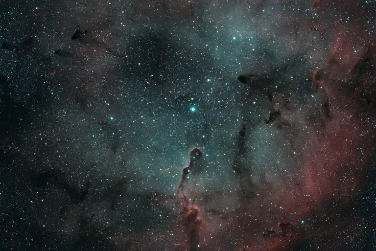
For example, here is a broadband image of Veil nebula
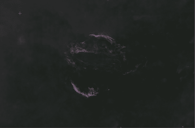
Veil is a broadband object, that we shoot in narrowband to exclude the abundance of light pollution and general brightness of the area to really focus on the diffuse gas around the nebula. When we think of “signal” it’s not as binary as some people suggest. So yes, again, when using a narrower 3nm vs a 5nm filter, the Signal of “Ha in comparison to sky glow” is higher, but the total signal of the image is lower than the wider filters per unit of time.
I show the Veil nebula because I want to remind people that not all signal is bad even if you are targeting specific wavelengths. A wider narrowband filter is picking up more valid target signal per unit of time but also more sky noise per unit of time.
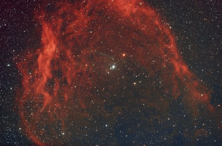
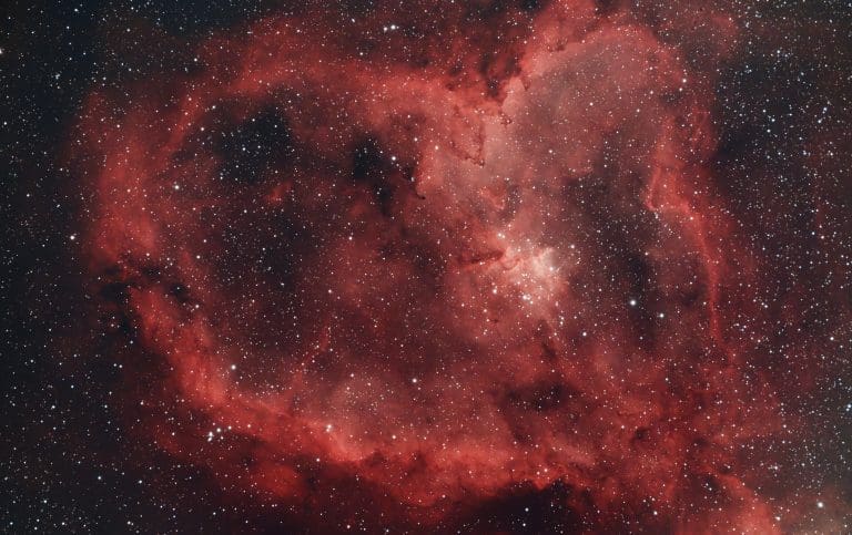
The reason one uses a Narrowband filter to begin with is to focus on intensities at specific wave lengths. Here is a 3nm Ha of the same region.
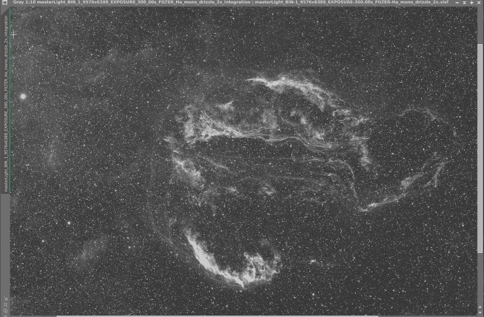
Clearly, you can see some more dust in contrast in some ways in comparison to the above RGB Image. This is partly because the filters have cancelled out enough of the competing light that I can capture greater intensities of the Ha signal. It took more time to get that Ha master than it did to get the RGB master. In both single sub exposures and total integration because the Ha filter is much narrower than the wider RGB filters. In comparison, the RGB image shows a lot more diffuse dust as a background vs trying to contrast it with a black background. The SHO filter is kind of oblivious to the intensity of dust clouds there that are often ignored on so many images in this region. (or we don’t allow long enough exposures in time to resolve their signal)
I’ll share an L master after I finish integrating it because it will show an intensity that is so amazingly rich you can see why some people just image in LRGB and only during clear nights. Still processing it, but back to the narrative.
The point is, while we do increase the “Ha to Background” the narrower filter still cuts some signal that may be advantageous or for lack of better words, “isn’t bad signal” – so keep that in mind.
A lot of people seem to think because we say, “Ha emission nebula” that it can only be seen in “Ha” filters. This is not true. The reason we use a Ha filter is to cancel out all the other frequencies of light and focus on the Ha signal. Some emission nebulae are so faint that the only way to discern them from brighter signal is to remove the competing bright signal and focus on them in NB. The Vail and many other nebulas are just bright in general. As a photographer, our job is to understand these trade-offs and I hope by showing the RGB image you can see some of those tradeoffs are beautiful dark and bright wispy clouds that even expensive Narrowband filters don’t pick up.
Not all “non targeted” signal is bad.
Oh, and shot noise.
So, the thing about shot noise, is it’s there, it’s a ratio no matter what. It’s the same ratio no matter what. I just want to spell this out to be clear.
Why does this matter?
Because a narrower 3nm filter collects overall less signal (even if more Ha vs sky noise), the proportion of shot noise to signal is higher on a narrower filter for a comparison of any given time. This is hard to describe, but relating it to a 300 second 5nm filter, it means you need to image longer to have the same shot noise on a 3nm. Around 500 seconds on 3nm vs 5nm for my scope/camera.
This isn’t all the bad in the end entirely since this shot noise is reduced in quadratic reduction during integration while the signal increases linearly. When I moved from 5nm to 3nm, I still wanted to start from the same noise basis, so I decided to trade off more time to optimize for the narrower filter.
But doesn’t that mean it’s worse?
No, adding more time doesn’t mean it’s worse.
It’s surprising that some might consider more time as detrimental, for several reasons.
In darker skies, the duration available for imaging increases compared to light-polluted skies. We still favor darker skies, don’t we? It’s undisputed that the results and signal-to-noise ratio are superior, right?
Indeed, using a narrower filter and thus adding more time isn’t a negative. In fact, it means that for your targeted H-alpha signal, you can achieve an approximate 40% boost in contrast relative to the background signal – For an whatever NB Signal you target. Important to remember this. The Ha signal isn’t improving, just the relationship to sky background when we compare a narrow filter with a wider filter. The total Ha in Both is already the same but now the shot noise (as a ratio of total noise in the image) has increased and the sky background has decreased.
Here’s a graphic to represent some of what we talk about, and this is through the eyes of a sensor just receiving signal. This to me is where confusion arises. The sensor just receives different ratios of signal.
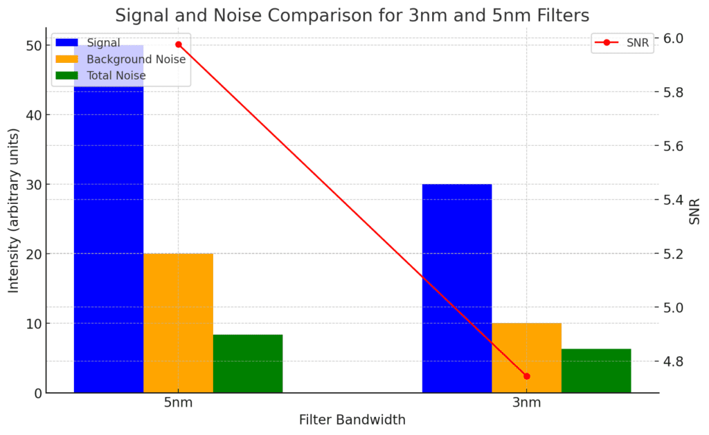
The important thing on the graphs isn’t necessary the numbers, but the ratios these numbers represent. So yes, the shot noise is lower, but the total signal is lower – that total signal includes the improved targeted NB contrast. When you divide the total signal by the shot noise, the ratio of shot noise per unit of time is higher on a narrower filter, so we equalize this by adding more time.
You may have noticed earlier, we said 3nm has a better SNR, but the graph shows otherwise. This initially seems counterintuitive because the narrower filter (3nm) is expected to have less noise. However, because the signal is much lower, the SNR does not improve without increasing exposure time (in comparison and as a sensor reads it). Again, ratio is important word here. So many people create the mental model of “well, we’re targeting SII, HI, OIII over sky glow better” and that = Better target SNR but again, the reality is this is only true if the SHOT noise in comparison is the same and for that, you need more time.
A lower sky glow in ratio to Ha, Oiii, Sii, is a good thing, but do we have a better word than SNR to talk about an improvement we champion that excludes the component of shot noise? SNR as a word is meaningless if it doesn’t include the shot noise component.
But there are other complications too 🙂 Swamping your sensor. One more thing
Dither
Before complicating matters further, there’s another technique we can use: dithering. Frequent and substantial dithering aids in the integration process, minimizing the effects of shot noise. I include this because for many, Dithering is a cost of time – but just like increasing your sub exposure times when you go narrow, increasing your dithering provides a benefit too. It’s totally worth it no matter the width of any filter, but even more so important in my opinion the narrower the filter. There are other benefits of dithering that I may write about in another blog post.
Now for swamping our sensor, I’ll just into the widely accepted swamp factor math.
Sharpcap Math for exposure time
Sharpcap has an amazing tool where you can plug your sensor and sky details into, and you get a e/pixel/s rate of sky glow. You can then do some math to figure out your optimum exposure time, so I’ll do this on a Bortle 1 sky with a .01 sky glow 3nm and .02 sky glow for 5nm to show how a 5nm vs a 3nm compares in just the sensor “Swamping” aspect of a narrower filter.
The formula is: Read Noise^2 * 10 divided by the e/pix rate of your sky. On my sensor, the read noise at gain 100 is 1.5e
5nm = 1.5^2 * 10 / .02
2.5 * 10 / .02 = 1250 seconds
3nm = 1.5^2 * 10 / .01
2.5 * 10 / .01 = 2,500 seconds
The reason that the 5nm has a higher sky glow of .02 is it allows ~40% more in, in comparison to the narrower filter only allowing .01% in.
This relationship is based on “Swamping your sensor” and you can then figure out that relationship to your stack size. Which, I may cover in another blog post.
I’ll come back and update this with the math on a higher Bortle sky so you can see the convergence at which point more time isn’t really necessary because the total signal rate is so high anyway.
What I like about the sharpcap math, is it removes some of the guessing of “What does it mean to go narrow”. It kind of creates a higher ceiling for being able to go longer in exposures and integration and you get the benefit of reducing the shot noise if you do. So regardless of how we frame the ratio of “Ha (Sii,Oiii) to sky noise” with a narrower filter, I think it’s wrong to drop the “shot noise” from the equation and the Sharpcap math just kind of settles it for all without having to split hairs on this.
It’s rather excessive in a B1 sky as you can see above, but for many people imaging in B4 or much high B6-B9 skies, the time factor difference between 3nm and 5nm becomes negligible.
Conclusion
Well, it even gets a bit more nuanced at times, but I hope this helped you understand some of the ramifications of going Narrow. I’ll wrap up by saying that we run 3nm on our Observatory and we get great images, shooting at slightly longer times. I think the tradeoff of time is worth it.
However, if you can’t afford any further time and already are in dark skies or if you prefer to collect Ha on very distance galaxies (where the signal is red shifted) a wider filter may be great for you.
I think a lot of confusion and a lot of debate stems from mental models around the color or label of a filter’s bandwidth and bandpass, so when we think we’re increasing the ratios of “Ha” vs “skyglow” we build a model irrespective of time or shot noise in our head but if you think of it is 5nm of bandwidth at a specific bandpass – without any labels, it becomes more intuitive. Additionally, when imaging bright nebula – not all signal is bad – even if we’re trying to target more specific signal. This means, not every nebula will see higher contrast with a narrower filter because the other light within the bandpass may be providing detail but if you image long enough to overcome the shot noise, you’re probably not worse off in any case.
Did we confuse everything more? I’m not sure. I appreciated the exercise in math and have some more charts to share as Learned a lot on the discussions and doing my homework.
I pretty much learned that the argument for either is largely an argument, but an answer we may be able to agree on is that with a narrower filter, the Ha increases in relationship to sky-glow if we don’t increase shot noise – the best way to solve the shot noise problem is to dither a bit more and image a bit more. Dithering wouldn’t harm wider filters either.
Image for a longer duration, dither more, and enjoy the resulting beautiful images. In writing this I’ve convinced myself further of the importance of bringing out the stunning features of nebulae and the combination of different wavelengths for superior imagery. The endless debates over “which filter is better” may not be as crucial as understanding that they are simply part of our extensive toolkit and the endless trade-offs we face. The most valuable lessons lie in grasping the knowledge of these trade-off for me are time and the tools at hand for the task. It also serves as a reminder of the peculiar nature of light.
Clear skies!